
AMADEVS: Generalized Aircraft Modeling & MDO Framework
🚀 Project Overview: AMADEVS
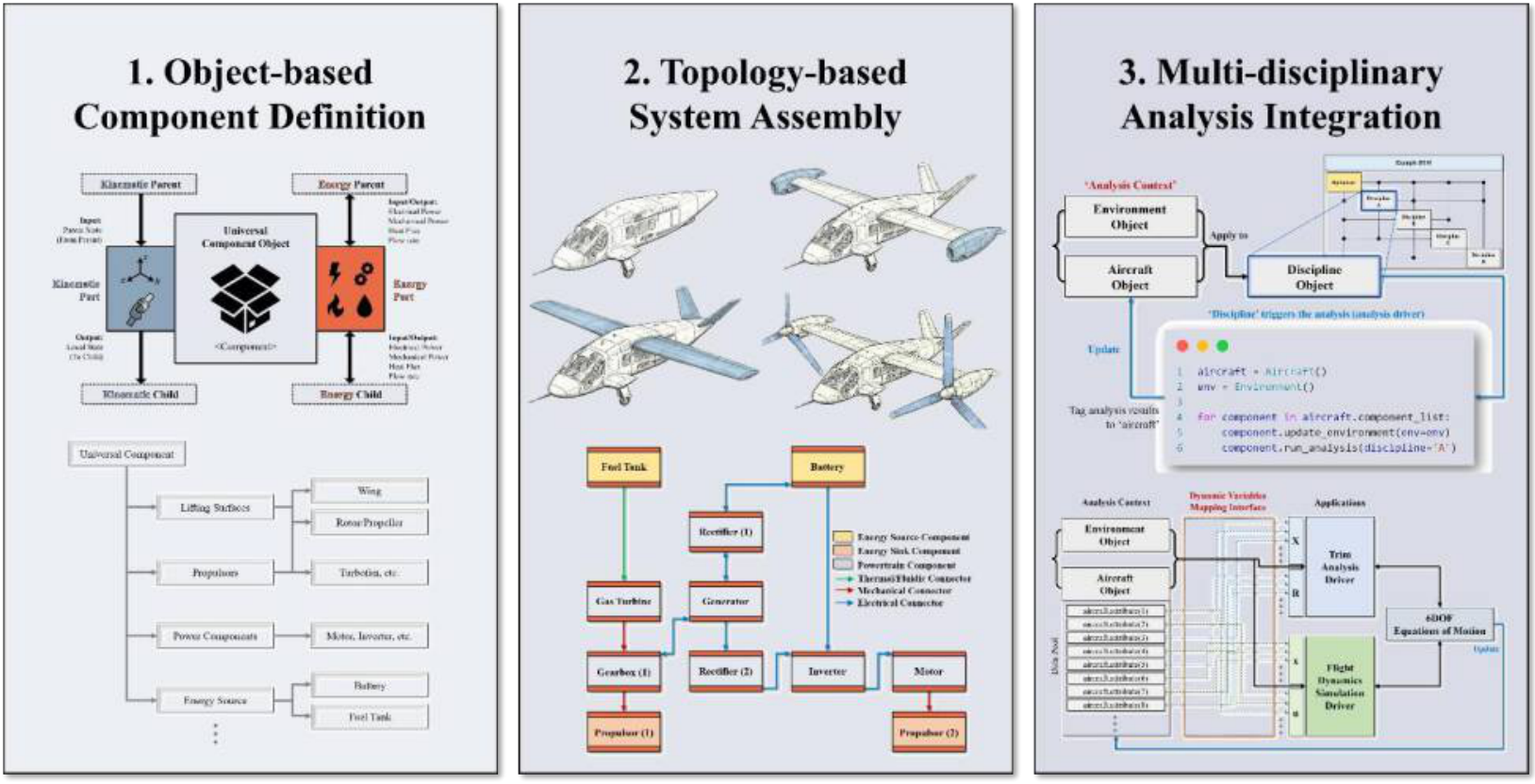
AMADEVS (Advanced Modeling, Analysis & Design Environment for Vehicle Systems) is a generalized framework developed at AVDL, SNU, for the multidisciplinary design and analysis of conventional and unconventional aircraft (eVTOL, UAM, tiltrotors, tailsitters, etc.).
Aircraft are built from role-based component objects connected through a dual geometry–energy topology, and aerodynamic, propulsion, flight-dynamics & control, and mission analyses all run on this single model. [Related Publication: AIAA 2026-1687]
🛠️ My Key Contribution: Propeller–Wing Interaction (PWI) & Wing Design Optimization
In distributed electric propulsion (DEP), the propeller slipstream strongly changes the wing’s lift and drag distributions, so designing the wing and propeller separately misses beneficial interference. I developed the PWI analysis and the coupled wing–propeller MDO workflow in AMADEVS.
1. Aero-Propulsive Coupling
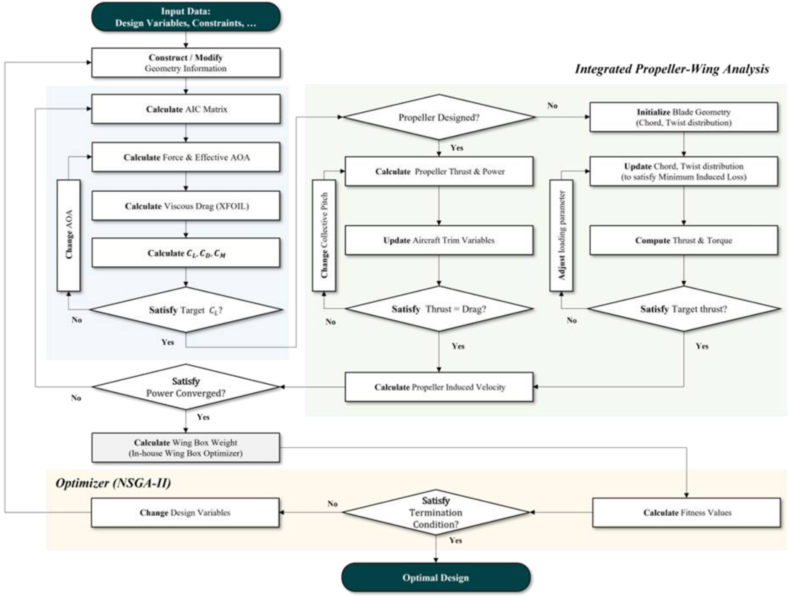
- Wing aerodynamics: in-house vortex lattice method (VLM) code; it supports free-wake unsteady simulation, and a steady formulation is used for optimization to keep the cost low.
- Propeller: blade element model based on Drela’s QPROP formulation.
- Coupling: the propeller-induced velocity field (Conway’s analytical slipstream model, following Alba et al.) is added at each VLM control point, capturing slipstream contraction and swirl instead of a uniform inflow.
2. Validation (PROWIM)
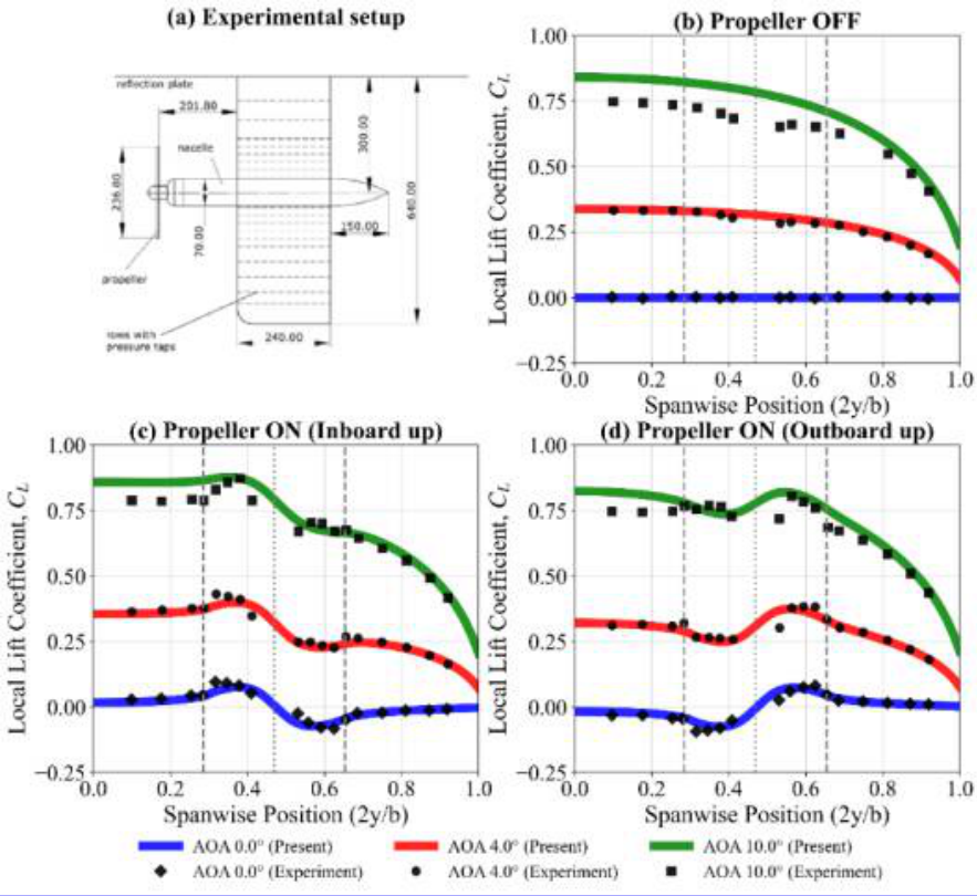
3. Bi-Objective Wing–Propeller MDO
- Configuration: X-57 Mod 2-like twin-propeller aircraft at cruise.
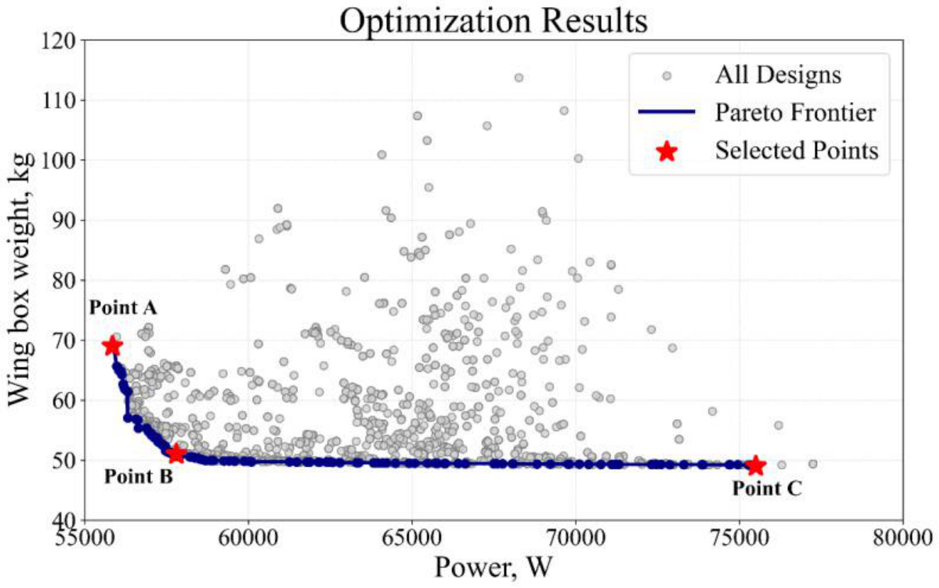
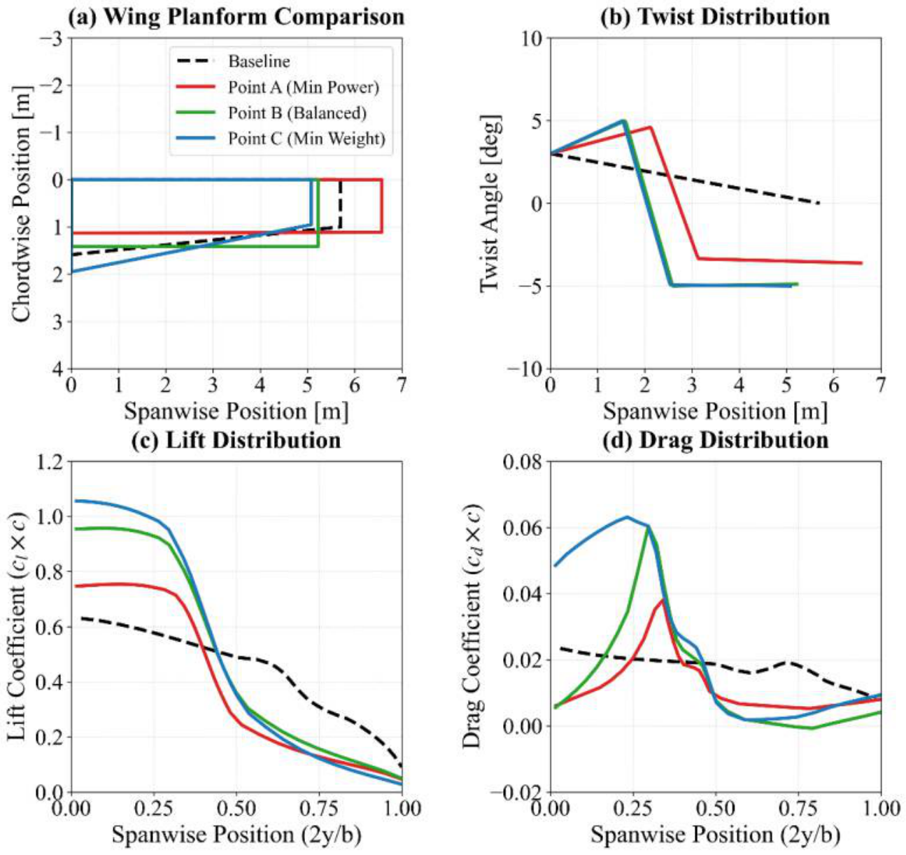
- Objectives: minimize cruise power and wing-box structural weight (in-house Euler–Bernoulli beam wing-box optimizer).
- Design variables (9): aspect ratio, taper ratio, three twist stations placed around the propeller, propeller spanwise location, radius, blade count, and rotation direction.
- Optimizer: NSGA-II; each candidate runs a coupled VLM–propeller trim loop (minimum-induced-loss propeller design and thrust–drag balance).
Key Findings
- There is a clear trade-off: high aspect ratio lowers induced drag but increases root bending moment and wing-box weight.
- The optimizer creates a sharp change in twist at the propeller: more incidence in the inboard upwash region tilts the lift forward to offset drag, and washout in the outboard downwash region moves the load inboard and reduces structural weight.
- The optimal propeller location depends on the balance between energy efficiency and structural weight, so the wing and propeller should be designed as one system.
📚 Related Publication
- Jeonghwan Kim, Seongjoong Park, Berenice Chatelain, Seonghyun Jeong, Jaehyun Ryu, Seunghyun Joo and Kwanjung Yee, “AMADEVS: A Generalized Aircraft Modeling & Analysis Environment for Multidisciplinary Design,” AIAA SCITECH 2026 Forum, https://doi.org/10.2514/6.2026-1687